User Valves
This command lets you to define a Valve component from base geometrical elements in the drawing.
Accessed by selecting the User Valve option from the Conformance Tools gallery.
Begin by using options from the Base Geometry toolbox to draw shapes for the valve (or select an existing shape in the drawing using one of the selection options.) Next select the User Valves option from the Conformance Tools gallery.
The Component Type Selection dialog will display. This dialog enables you to assign a valve type to the selected geometrical shape(s).
Next a User Component Options dialog (similar to below) displays prompting you to provide the Active Angle for the valve as shown below:
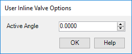
Define the Active Angle and click OK to display the valve Properties dialog, which will be specific to the valve type selected.
Assign a tag number for the valve and define the remaining properties as needed. When finished click OK to complete the process.
Annotation
The new component can be annotated using the Annotation dialog. Right-click on the component and select the Annotate option from the context menu.